ROS 2 on a Raspberry Pi Robot

This post shows how to use ROS 2 to control the CamJam EduKit #3. It uses a Raspberry Pi Zero 2W, which is a small development board with minimal compute power. However, the Pi Zero can still run a full Linux Operating System, which makes it a great entry point into building your own cost-effective robot. All instructions should be applicable to more powerful Raspberry Pi models, such as the 4 or 5 models.
The CamJam EduKit #3 is a cheap robot kit you can use to build your robot. I have a series of videos on YouTube of how to assemble and run the kit, and a blog post that will tell you what each video is for. It comes with a series of worksheets to get to following a line course or avoiding obstacles; this post aims to combine the line following with obstacle avoidance, while using ROS 2 to read the sensors and move the robot.
This post is also available in video form. If you'd prefer to watch, click the link below:
Why use ROS 2?
The EduKit comes with worksheets and sample Python code for controlling the robot without ROS 2, so why bother to install ROS 2 at all?
The short answer is that ROS 2 isn't that useful for a simple robot like this one, but it paves the way for us to add more complexity in, and it does have some useful benefits. For example, it becomes much easier to add more sensors to the robot, or control the robot using a gamepad plugged into another computer on the same network as the Pi. This is how we were able to use a keyboard to move the JetBot around.
In this case, we will use it to continuously publish the sensor data from both the distance sensor and the line sensor, then have separate nodes to determine how to move the robot and to translate movement commands into moving the wheels.
If you're brand new to ROS 2, check out my Getting Started with ROS 2 post, which talks about the key concepts of ROS 2 and why you might want to learn it for yourself. From there, you can start to learn from the official tutorials or other posts on this site.
With a better idea of why we want to use ROS 2, let's take a look at how to set it up on the Raspberry Pi Zero.
Setting up ROS 2
The easiest way to set up ROS 2 on Ubuntu is to install the binaries using
apt, as described in the rest of this section. However, if you aren't using
Ubuntu, you can either install from
source,
or use
Docker.
I tried to write this post with extra instructions for Docker and Podman, so that anyone using a Pi Zero running Raspberry Pi OS (or those that just prefer Docker) could still follow along.
The container could build the workspace, but not run it; it was too much work and the board would crash. Feel free to try for yourself - you may have better luck! You can find out more about how to build a suitable Docker image in this post on Running ROS 2 on Raspberry Pi 5.
The reason I used Ubuntu for my Raspberry Pi so far is to make it easier to install ROS 2 now, so if you've been following along, it should be easy!
To install ROS 2, you can follow the instructions for your board depending on the version of Ubuntu you are running:
- Ubuntu Jammy (22.04): ROS 2 Humble or Iron
- Ubuntu Noble (24.04): ROS 2 Jazzy
I reflashed my own board to use Ubuntu Noble, so I use the installation instructions for ROS 2 Jazzy. You can also take a look at the instructions for ROS 2 on Raspberry Pi.
SSH Connection
Open a terminal, such as Command Prompt on Windows or Terminal on Linux. If you are using Linux or Mac, you should have SSH already available. If you are on Windows, try to install OpenSSH following these instructions.
In the past, I used VSCode over SSH to edit and run scripts on the robot. For installing ROS 2, I recommend using a terminal to SSH instead. The board is not very powerful, so running any ROS 2 command has a high chance of freezing and restarting the board - at least from my own testing.
If you're on a more powerful version of the Raspberry Pi, you can ignore this warning!
Once complete, make sure your computer and the Raspberry Pi are both on and
connected to the same network. SSH in to the board using ssh user@rpi0 - these
will depend on the username and hostname that you set while flashing the board.
For me, this is ssh mike@rpi0.
All commands from here on are run in the SSH session with the Raspberry Pi. If the board goes down, keep trying to SSH in again until it accepts the connection.
System Setup
To enable the required repositories, execute the following commands:
sudo apt install software-properties-common
sudo add-apt-repository universe
Add the ROS 2 GPG key:
sudo apt update && sudo apt install curl -y
sudo curl -sSL https://raw.githubusercontent.com/ros/rosdistro/master/ros.key -o /usr/share/keyrings/ros-archive-keyring.gpg
Then add the repository for ROS 2. We added the GPG key so that the board will connect to this repository without errors.
echo "deb [arch=$(dpkg --print-architecture) signed-by=/usr/share/keyrings/ros-archive-keyring.gpg] http://packages.ros.org/ros2/ubuntu $(. /etc/os-release && echo $UBUNTU_CODENAME) main" | sudo tee /etc/apt/sources.list.d/ros2.list > /dev/null
With all the system dependencies installed, it's time to install ROS 2 itself.
Installing ROS 2
First, make sure the system is up to date after adding the new repositories. This may take some time if you've not done it after flashing:
sudo apt update && sudo apt upgrade -y
For this tutorial, we will need the right ROS 2 version and the dev tools.
Replace jazzy with your version of ROS 2 for these instructions.
sudo apt update && sudo apt install ros-dev-tools ros-jazzy-desktop
Again, this is likely to take some time. Once complete, you should be able to run the following command:
source /opt/ros/jazzy/setup.bash
If this works, you're in good shape to start checking out the code! If not, make sure you installed the right packages above, and take a look at the installation instructions to see if you (or I) missed anything.
Running this source /opt/ros/jazzy/setup.bash command is important to be able
to run any ROS 2 command. If you open a new SSH session, or the board restarts
for any reason, make sure to run this command again.
Enabling Access to RPi.GPIO
To be able to access the GPIO on the Raspberry Pi, which is required to read the sensors and turn the motors, we first need to install the library:
sudo apt install -y python3-rpi.gpio
We then need to give our user permission access to the GPIO on the board, so that we can run ROS 2 nodes. To do so, execute the following:
sudo usermod -a -G spi $USER
sudo usermod -a -G gpio $USER
sudo usermod -a -G i2c $USER
Then edit the file /etc/udev/rules.d/99-com.rules as root. You could do this
by executing sudo nano /etc/udev/rules.d/99-com.rules. Give it the following
contents:
SUBSYSTEM=="spidev" , GROUP="spi" , MODE="0660"
KERNEL=="i2c-0"     , GROUP="i2c" , MODE="0660"
KERNEL=="i2c-[1-9]*", GROUP="i2c" , MODE="0660"
KERNEL=="gpiomem"   , GROUP="gpio", MODE="0660"
Activate the new permissions by executing this command:
sudo udevadm control --reload-rules && sudo udevadm trigger
Then, log out and back in again. This should be all the configuration needed.
With ROS 2 installed and the system configured, let's take a look at how to download and build the source code.
Building the CamJam Packages
Creating a Workspace
ROS 2 uses workspaces to keep track of everything it needs for a robotics
application. You can use any folder you want as a workspace, but I tend to use
ros2_ws as the workspace name, where ws stands for workspace. If you want to
use another name, you can edit the commands below with the new name.
First, create the workspace folders and change directory into the src folder.
mkdir -p ~/ros2_ws/src
cd ~/ros2_ws/src
Then, clone the packages for the CamJam into the src folder. Each package
contains one or more nodes which are useful for running the robot. By cloning
each one, we can build everything together in the same workspace and be able to
launch it all at the same time.
git clone https://github.com/mikelikesrobots/camjam_sensors.git src/camjam_sensors
git clone https://github.com/mikelikesrobots/camjam_control.git src/camjam_control
Building the Workspace
Next, build the code using colcon. The --symlink-install means that Python
files are linked instead of copied, which means that changes in the original
will be reflected in the output. Normally, the files are copied, which means
that editing the original has no effect on the copied file.
cd ~/ros2_ws
colcon build --symlink-install
The output should look something like this:
Starting >>> camjam_control
Starting >>> camjam_sensors
Finished <<< camjam_sensors [19.7s]
Finished <<< camjam_control [20.0s]

Summary: 2 packages finished [22.1s]
If the packages built successfully, we are able to start running!
Running the Robot Software
Once we've built the workspace, we need a second source command:
source install/setup.bash
This is the command that sets up our ROS 2 environment, so that when we run ROS 2 commands, it knows where the required files are.
With that complete, make sure that the motor power is on and execute the following:
ros2 launch camjam_control camjam_control.launch.py
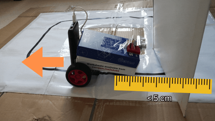
The section on Explaining the Code goes over how this works in more detail, but essentially it launches all of the nodes for the sensors, main behaviour, and wheel control. Once this has had time to start up, the robot will start trying to follow a line. Put it on a line course and see how it does!
![]()
Here are some of the logs from running my own robot around the course:
[control-3] [INFO] [1738250012.724674335] [camjam01.controller]: Found line! Following...
[control-3] [INFO] [1738250012.844485123] [camjam01.controller]: Lost line! Finding...
[control-3] [INFO] [1738250013.474098541] [camjam01.controller]: Trying right...
[control-3] [INFO] [1738250014.034229698] [camjam01.controller]: Found line! Following...
[control-3] [INFO] [1738250014.094463606] [camjam01.controller]: Lost line! Finding...
[control-3] [INFO] [1738250014.674026633] [camjam01.controller]: Trying left...
[control-3] [INFO] [1738250015.544929398] [camjam01.controller]: Found line! Following...
[control-3] [INFO] [1738250015.604943673] [camjam01.controller]: Lost line! Finding...
[control-3] [INFO] [1738250016.274049901] [camjam01.controller]: Trying right...
[control-3] [INFO] [1738250017.324330833] [camjam01.controller]: Found line! Following...
[control-3] [INFO] [1738250017.434205724] [camjam01.controller]: Lost line! Finding...
[control-3] [INFO] [1738250018.073983312] [camjam01.controller]: Trying left...
[
Line following is not all the robot does; it also avoids obstacles. If you put something large in front of the robot, it will back away until it's far enough to resume searching for the line.
Here are some of my logs from the robot trying to avoid obstacles:
[control-3] [INFO] [1738250039.426828548] [camjam01.controller]: Obstacle too close - avoiding!
[control-3] [INFO] [1738250039.473658732] [camjam01.controller]: I'm avoiding an obstacle...
[control-3] [INFO] [1738250039.674483211] [camjam01.controller]: I'm avoiding an obstacle...
[control-3] [INFO] [1738250039.684512502] [camjam01.controller]: Obstacle too close - avoiding!
[control-3] [INFO] [1738250039.873822858] [camjam01.controller]: I'm avoiding an obstacle...
[control-3] [INFO] [1738250039.929521770] [camjam01.controller]: Obstacle cleared. Looking for line...
And that's it! We have successfully installed ROS 2, downloaded and built packages for controlling the CamJam EduKit #3, and run an application that follows a line while avoiding obstacles.
Let's take a closer look at how the code works.
Explaining the Code
The code is split into two packages: camjam_control and camjam_sensors. Each
package contains two nodes.
The camjam_sensors package contains the two sensor nodes, and the camjam_control package contains the controller and movement nodes. These are illustrated below:
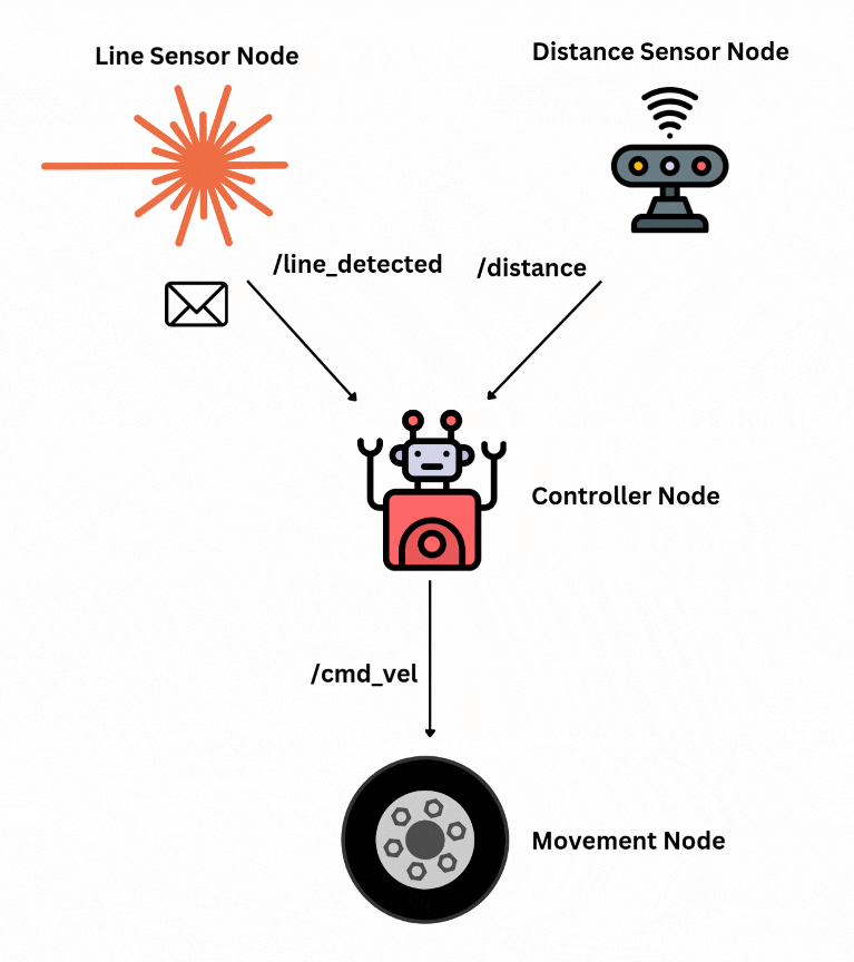
Let's take a look at each package in turn to build up our understanding of how ROS 2 nodes can interact with each other.
camjam_sensors
The camjam_sensors
package contains two ROS 2 nodes inside a ROS 2 package. Most of the files in
the repository are to help colcon build the package correctly:
resource/camjam_sensors: A marker file copied to the ROS 2 package index, so that ROS 2 knows this package existsLICENSE: A file with a permissive licence allowing any viewer to use the code however they wishREADME.md: A small file to say what the repository is and how to use itpackage.xml: Defines the package name and dependencies forcolconsetup.cfg: A configuration file for the Python package to define where scripts should be installedsetup.py: A standard setup script for a Python package, defining the files that are required for correct functioning of the package
The camjam_sensors folder contains the code that we are more interested in.
There are three files here. The first, __init__.py, is a blank file that
Python needs to understand that there are other files in the directory. Let's
take a look at the other two files in more detail.
line_sensor.py
The node for the line sensor is a good place to start to understand the structure of a ROS 2 node.
At the top, we import all of the libraries needed to build a node and control the line sensor pins:
import rclpy  # The ROS 2 package
from rclpy.node import Node  # The Node we use to build the Line Sensor class

from std_msgs.msg import Bool  # The message type we publish from the node
from RPi import GPIO  # The library needed to access the line sensor pins
import time  # An extra library used in the code for sleeping
We also set the default line pin sensor as pin 25:
DEFAULT_PIN_LINE_SENSOR = 25
Next, we declare that the LineSensorPublisher is a Node. It has the __init__,
_is_line_detected, and timer_callback functions. It works by creating a
timer that will call the timer_callback function every 10 milliseconds. The
callback then checks if a line exists with _is_line_detected and publishes
that value in a message.
The __init__ method is what sets this all up. This method is the first method
called when building an instance of a Python class. In this case, it begins by
declaring and accessing a
parameter:
self.declare_parameter("line_sensor_pin", DEFAULT_PIN_LINE_SENSOR)
self._line_sensor_pin = self.get_parameter("line_sensor_pin").value
This states that the line sensor pin should be pin 25 by default, but can be overridden by a user using the node. That in turn means that a user can use the line sensor on a different pin, making it possible to add extra line sensors without changing the code. With this configuration, you can launch two nodes with different pin configurations to access two different line sensors!
Next, the node sets up the GPIO to access the line sensor. This should look familiar from the EduKit code for the line sensor.
self.get_logger().info("Setting up pins for line sensor")
GPIO.setmode(GPIO.BCM)
GPIO.setwarnings(False)
GPIO.setup(self._line_sensor_pin, GPIO.IN)
The node then sets up the publisher and timer. The
publisher
is an object that can be used to publish ROS 2 messages of a particular type to
a particular topic - in this case, the Bool
message,
published to the line_detected topic.
self.publisher_ = self.create_publisher(Bool, "line_detected", 10)
The node sets up a ROS 2
timer
that calls the timer_callback function every 0.01s, giving us our sensor
readings every 10 milliseconds.
timer_period = 0.01
self.timer = self.create_timer(timer_period, self.timer_callback)
That's it for initialisation! Now, the node is set up to call
timer_callback
every 0.01s:
def timer_callback(self):
    msg = Bool()
    msg.data = self._is_line_detected()
    self.publisher_.publish(msg)
As in the code above, the timer callback will call the _is_line_detected
function to determine if a line is detected, then publish that in a message.
_is_line_detected
just reads the pin for the line sensor, exactly as written in the EduKit
worksheet.
def _is_line_detected(self) -> bool:
    return GPIO.input(self._line_sensor_pin) == 0
Finally, the rest of the file contains a main
function
that constructs a LineSensorPublisher object and runs it until the node is
shut down. This is accomplished by using the rclpy.spin function, which takes
a node and runs it until the process is shut down.
def main(args=None):
    # Initialise rclpy
    rclpy.init(args=args)
    # Build a line sensor object
    line_sensor = LineSensorPublisher()
    # Run it until rclpy shuts down
    rclpy.spin(line_sensor)
    # Do any cleanup before exiting
    line_sensor.destroy_node()
    rclpy.shutdown()
That's all for the line sensor. Let's use what we've learned to understand a slightly more complex sensor-reading ROS 2 node: the distance sensor (the HC-SR04).
hcsr04.py
The node for the distance sensor is similar to the line sensor, so this section will describe the important differences.
First, this node published Range
messages
instead, which changes the import
code:
from sensor_msgs.msg import Range
It also changes the
publisher
to publish Range messages on the distance topic instead.
self.publisher_ = self.create_publisher(Range, "distance", 10)
There are more pins required for the distance sensor as well, which means there are more default pins, more declared parameters, and more GPIO setup.
The timer_callback function is very
similar,
except that it uses the _read_distance function to get a distance measurement
and publishes a Range measurement instead.
def timer_callback(self):
    msg = Range()
    msg.range = self._read_distance()
    if msg.range is not None:
        self.publisher_.publish(msg)
The _read_distance
function
is quite a bit larger because it has some timing to check the pulse length, so
it's not included here. The important point to note is how close it is to the
original code from EduKit.
The rest of the file is the same parameter declaration setup and main function as for the line sensor.
Summary
The camjam_sensors package contains two nodes. One reads whether the line
sensor is detecting a line and publishes a Bool message on the line_detected
topic every 0.01s (100 Hz). The other node reads the distance sensor and
publishes Range messages on the distance topic every 0.25s (4 Hz).
Both are set up with parameters controlling the pins used, so that if extra sensors are attached or the pins are changed, a user can change the pins used.
If you want some practice with working with ROS 2, see if you can modify these nodes to have their timer periods read from parameters, so that a user can speed up or slow down the measurements.
camjam_control
This package has a similar setup to camjam_sensors, so I
will skip all of the package files and go straight to the source files in the
camjam_control directory. However, there is a new file called
launch/camjam_control.launch.py, which is discussed in a later
section.
camjam_movement.py
As with the camjam_sensors package, this node uses RPi.GPIO to control the
pins for the motors. However, this time it uses PWM to send a signal (see my
explanation of PWM and I2C here). This means 4 pins
worth of parameters, plus an extra couple to control the PWM frequency and
maximum duty cycle.
DEFAULT_PWM_FREQUENCY = 20  # Hz
DEFAULT_FULL_SPEED_DUTY_CYCLE = 40  # %
Between the pin configuration and maximum duty cycle, the user can decide which pins correspond to which motors and what max speed on the robot looks like.
With these pins and PWM frequency parameters, the node sets up the PWM signals.
self._motor_a_fwd = GPIO.PWM(motor_a_pin_fwd, pwm_frequency)
self._motor_a_rev = GPIO.PWM(motor_a_pin_rev, pwm_frequency)
self._motor_b_fwd = GPIO.PWM(motor_b_pin_fwd, pwm_frequency)
self._motor_b_rev = GPIO.PWM(motor_b_pin_rev, pwm_frequency)
The last step in the __init__ function of this node is to set up a
subscriber.
Subscribers listen for messages instead of publishing them, and when they
receive one they call a callback function to decide how to handle it. In this
case, the movement node subscribes to cmd_vel topic for Twist
messages,
and when one is received, it calls the _vel_callback function.
self.vel_sub_ = self.create_subscription(
    Twist,
    "cmd_vel",
    self._vel_callback,
    10  # This means 10 messages can be queued up to be handled
)
Twist messages contain information about the requested velocity of the robot.
It defines linear movement and angular movement. This robot can only move in the
x direction linearly, meaning forwards and backwards, and can only rotate
around the z axis, meaning turning left and right. Therefore, the
_vel_callback
function
calculates values for the left and right wheels based on linear.x and
angular.z, then sends those values as PWM signals to the motors.
def _vel_callback(self, msg: Twist):
    fwd = msg.linear.x
    turn = msg.angular.z
    # A bit of forward and turn, limited to a speed of 1
    right = min(1, fwd - turn / 2)
    left = min(1, fwd + turn / 2)
    # Multiply by maximum duty cycle for speed
    left = int(left * self._full_speed_duty_cycle)
    right = int(right * self._full_speed_duty_cycle)

    # If positive, send to fwd wheel, else send negative to reverse wheel
    if left >= 0:
        self._motor_b_fwd.ChangeDutyCycle(left)
        self._motor_b_rev.ChangeDutyCycle(0)
    else:
        self._motor_b_fwd.ChangeDutyCycle(0)
        self._motor_b_rev.ChangeDutyCycle(-left)

    if right >= 0:
        self._motor_a_fwd.ChangeDutyCycle(right)
        self._motor_a_rev.ChangeDutyCycle(0)
    else:
        self._motor_a_fwd.ChangeDutyCycle(0)
        self._motor_a_rev.ChangeDutyCycle(-right)
camjam_controller.py
This file defines the node that brings it all together. It listens for sensor
readings, decides how the robot should move, then sends that command to the
movement node using the cmd_vel topic.
The node works by keeping a state of what it should currently be doing, which is one of:
find_linefollow_lineavoid_obstacle
When any data arrives from the sensors, the state is changed depending on the sensor value.
Assuming the robot is trying to find or follow the line, a line sensor reading will change its state depending on whether the line is present or not.
if msg.data:
    if self._mode == "find_line":
        self.get_logger().info("Found line! Following...")
    self._line_miss_count = 0
    self._mode = "follow_line"
else:
    if self._mode == "follow_line":
        self.get_logger().info("Lost line! Finding...")
        self._direction_change_limit = self._starting_search_size
    self._line_miss_count += 1
    self._mode = "find_line"
The code says that if the robot is currently finding the line, and the line sensor detects a line, that means the line has been found and should be followed. The state is changed accordingly. The reverse happens if the line is lost. The other variable changes will be explained in the line search section.
For the range messages, if a range message is received and an obstacle is too close, the robot should avoid it no matter what state it is in. However, if the robot is already avoiding an obstacle and a range message says there is no obstacle close, the robot can go back to trying to find and follow the line.
def _range_msg_callback(self, msg: Range):
    if msg.range <= self._avoid_range:
        self._mode = "avoid_obstacle"
        self.get_logger().info("Obstacle too close - avoiding!")
    elif self._mode == "avoid_obstacle":
        self._mode = "find_line"
        self._direction_change_limit = self._starting_search_size
        self.get_logger().info("Obstacle cleared. Looking for line...")
The controller uses a timer to run a control loop every so often - 5 Hz by default, controllable by parameter. The state is determined by the sensors, which means that the control loop just needs to decide how to drive based on the current state.
If it's avoiding an obstacle, it backs away.
if self._mode == "avoid_obstacle":
    # Back away slowly
    cmd.linear.x = -self._reverse_speed
    self.get_logger().info("I'm avoiding an obstacle...")
If it's following the line, it goes forward at a set speed.
elif self._mode == "follow_line":
    # Follow the line!
    cmd.linear.x = self._follow_speed
Finally, if the robot is trying to find the line, it moves left or right to search for it.
if self._search_direction == "left":
    cmd.angular.z = self._turn_speed
else:
    cmd.angular.z = -self._turn_speed
Finally, it publishes the Twist
message,
which will be received by the movement node to actually move the robot.
self.publisher_.publish(cmd)
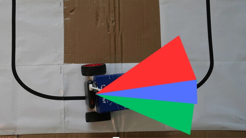
Search Algorithm
The robot uses a slightly more complex version of finding the line than the EduKit version. It tracks whether it should be looking left or right, but it also tracks how many range readings it has had while looking left or right, which determines how big an area it has searched for the line.
If the number of range measurements reaches a limit, the robot will change search direction.
if self._search_direction == "right":
    self.get_logger().info("Trying left...")
    self._search_direction = "left"
else:
    self.get_logger().info("Trying right...")
    self._search_direction = "right"
On top of this, the limit for how far to search for the line increases over
time, controlled by the search_increment and starting_search_size
parameters. The robot searches until it has received starting_search_size
range measurements, then increases the limit by
search_increment.
This means that the robot moves left, then more to the right, then more still
to the left. This allows the robot to find the line quickly if it's close, but
eventually find the line if it has moved far away.
self._direction_change_limit += self._search_increment
camjam_control.launch.py
This is the file that launches everything from both packages to move the robot. It is very simple, as it simply declares each node that should be run as part of the launch, such as the distance sensor node:
Node(
    package='camjam_sensors',
    namespace='camjam01',
    executable='distance',
    name='distance',
),
The launch file can do a lot more, though. For example, it can change parameters
and topic mappings. If you wanted to add a second line sensor, you could add
another Node that changes the pin configuration using parameters, and changes
the topic it publishes to from line_detected to right_line_detected.
There is a parameter set in this file which changes the maximum speed the robot can drive at. Try changing this parameter to control how fast your robot moves around the line following course.
Node(
    package='camjam_control',
    namespace='camjam01',
    executable='move',
    name='movement',
    parameters=[
        {"max_duty_cycle": 50},
    ]
),
Deep Dive Recap
Between two packages, we have:
- a node publishing line sensor readings at 100 Hz rate
- a node publishing distance sensor readings at 4 Hz rate
- a movement node that understands how to move the motors of the robot based on
messages on
cmd_vel - a controller that uses sensor readings to determine what the robot should do before publishing motor speed requests to the movement node.
One package also contains a launch file, which we can use to launch all the nodes at the same time, plus reconfigure them. We could change pins used for the nodes, the speed of the robot, or even add extra sensors and launch nodes to control them using this file.
Overall Summary
In this post, we saw how to run ROS 2 on a Raspberry Pi Zero 2W to control the CamJam EduKit #3 robot. Using ROS 2, we were able to program the robot to follow a line while also backing away from any obstacles it finds.
Using ROS 2 isn't necessary for an application this simple, but it does help to separate out code into different nodes. It also means we could scale up to add more sensors more easily, give our code to other people, or even control the robot with a gamepad or keyboard.
We saw how to install ROS 2 on the Raspberry Pi, check out and build the workspace, and run the launch file. This spawns ROS 2 nodes that will read both sensors, decide how to move the robot, and move the motors to accomplish the line following and obstacle avoidance.
Finally, we took a deeper look into how ROS 2 packages and nodes are structured, working up from the simplest example in the line sensor to a full controller node with increasing search area to locate and follow a line, plus back away from obstacles as they appear.
Give the code a try for yourself, and if you're feeling ready to challenge yourself, try to add more parameters to configure the ROS 2 nodes.